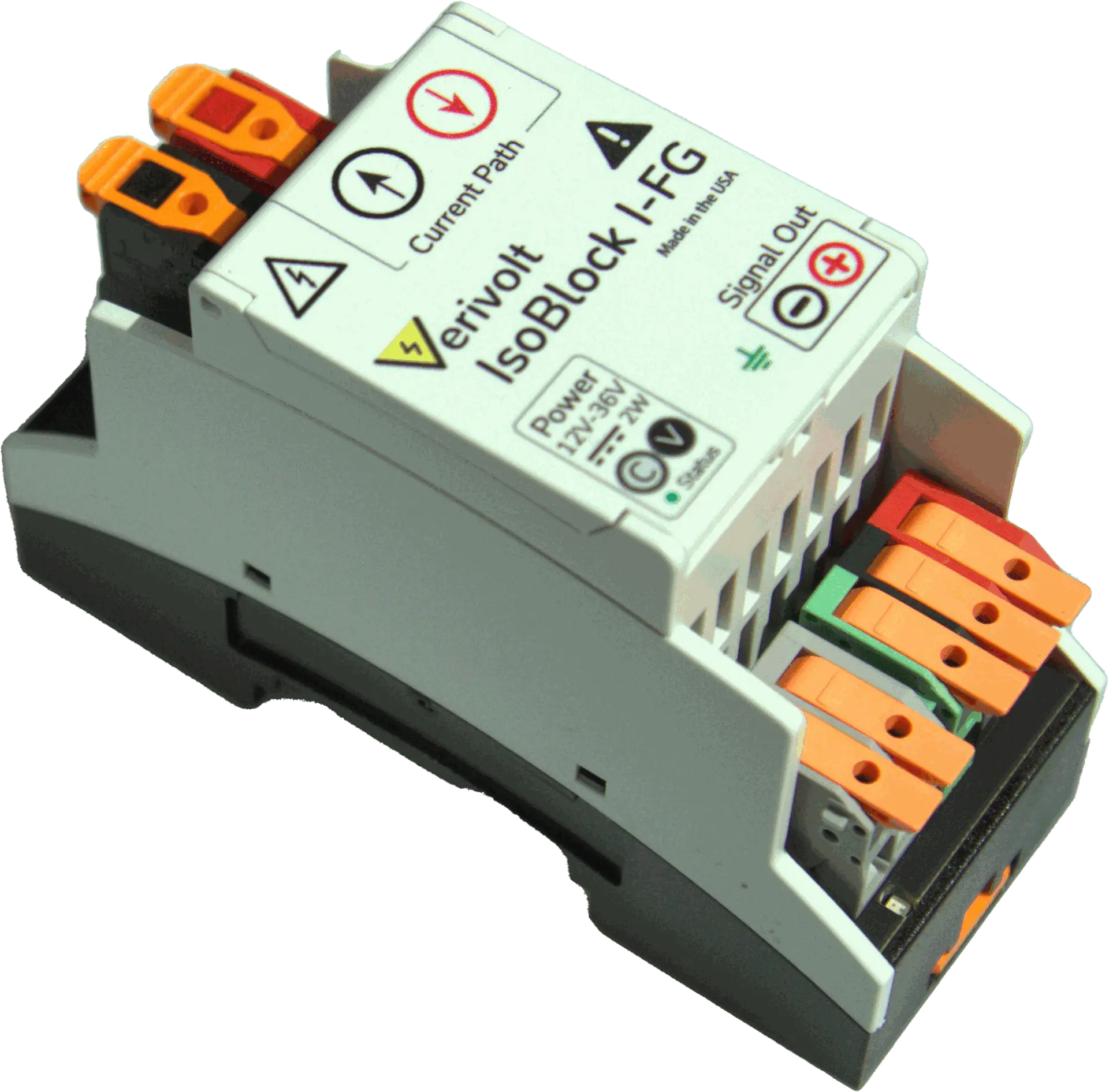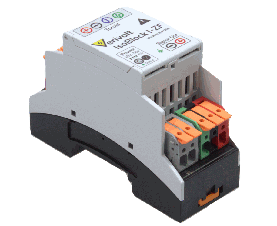

IsoBlock I-ZF
Features1,500v Sustained And 5,000v Peak Isolation
3 Way Galvanic Isolation
Dc To 100khz Bandwidth
Drop In Current Sensing To Any Daq
Ultra High Performance With 0.1 And 0.02% Accuracy.


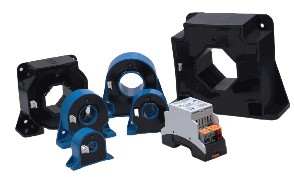
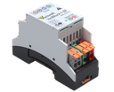
The IsoBlock I-ZF is a sensor designed for high-performance current measurements with ranges from 20A to 2000 Amperes. The IsoBlock I-ZF consists of 2 parts, a toroid and a DIN rail mounted conditioning unit. As all devices from the IsoBlock family it has an anti-aliasing filter and a conditioning stage to output a ±10V signal. The sensing unit uses Hall Effect with closed loop methodology to measure the current flowing in the conductor passing through the aperture. This is followed by translation, corrections, scaling and anti-aliasing filter in the conditioning unit.
Three-Way Galvanic Isolation
The IsoBlock I-ZF is a non-contact sensor that inherently provides primary-to-secondary isolation, which allows users to monitor a miscellaneous of currents at different potentials.

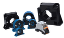
Compact Form Factor
The compact form factor of the IsoBlock I-ZF module set allows users to setup high channel density monitoring systems, making it ideal for high performance compact systems.
FAQ
Yes, the IsoBlock I-ZF can measure both AC and DC currents, if they fall within the specified bandwidth in the attached datasheet.
The sensor’s accuracy is defined by one of the following formulas:
±(0.1% of reading + 0.005% of range) or ±(0.02% of reading + 0.005% of range), depending on the level of accuracy selected for the module.
For example, with an IsoBlock I-ZF (100A, 10V, 0.1%), a 50A current would result in an accuracy of: (0.1% × 50A) + (0.005% × 100A) = ±0.055 A.
RMS vs. Peak Notation (AAC vs. A): We use AAC to indicate RMS current and A for peak current. This helps users avoid manual conversions. For example, 100A corresponds to 100 A peak input, while 100AAC corresponds to100 A RMS input ≈ 142 A peak.
An IsoBlock I-ZF (100AAC, 7VAC) has a 142 A peak current range and a 9.94 V peak output.
The IsoBlock I-ZF (50A, 10V) has a 5:1 conversion ratio. For instance, 5A will output 1V, -5A will output -1V, and 12.5A will output 2.5V. Furthermore, the accuracy of this measurement will correspond to the previously detailed accuracy formula: ±(0.1% of reading + 0.005% range).
The IsoBlock I-ZF (20A, 10V, 0.1%) can measure currents for ±20A and proportionally output a voltage of ±10V. The 0.1% accuracy of the sensor applies for the upper 10% of the range, which means that the sensor can accurately measure currents from ±2A up to ±20A. This result can be obtained when applying the following formula:
Accuracy = ± (0.1% reading + 0.005% range)
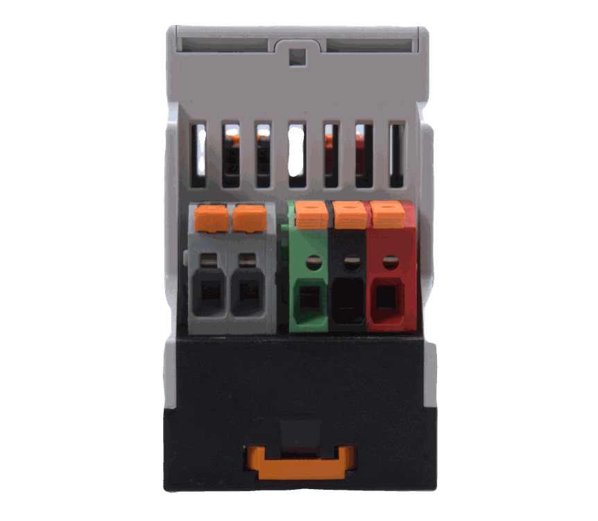
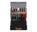
The IsoBlock I-ZF does not come with a prebuilt cable for the connection between the toroid and signal conditioning unit. However, it comes with the connector housing and crimping terminals to allow customers to build their own cable according to their requirements. The applicable cable area range is from AWG28-AWG22.
Additionally, we recommend that the cable between the two components has a length under 10 meters, in order to avoid any significant EMI or noise from affecting the measurements. For longer cables, it will depend on the environmental conditions in which the sensor is located in.