


Documentation


Product Details
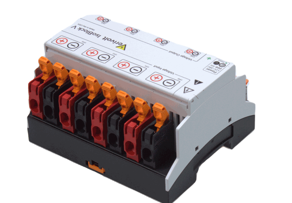
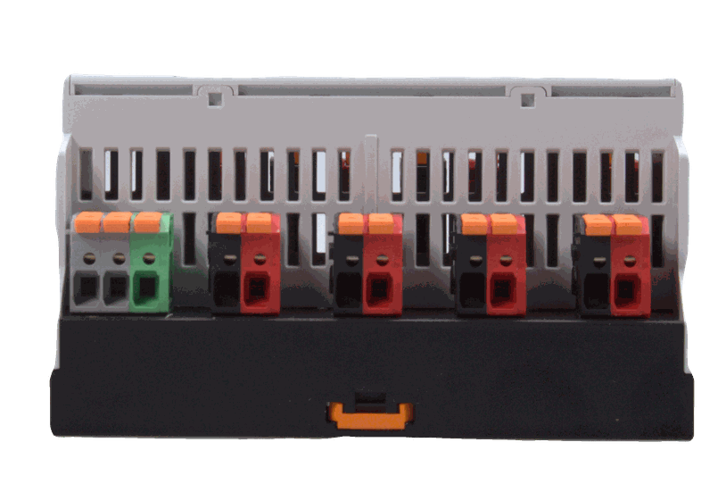
Four-Channel Isolated Differential Voltage Sensor
The IsoBlock V-4c delivers four synchronized, galvanically isolated voltage measurement channels in a single compact module. IsoBlock V-4c measures differential voltages from ±10mV to ±1500V with selectable accuracy: standard ±(0.2% of reading + 0.005% of range) for industrial applications, or precision ±(0.1% of reading + 0.005% of range) for validation and metrology work. The module outputs four independent differential ±10V signals (±5V custom option) with 100kHz bandwidth (100-300kHz custom option available), capturing both DC and AC components on all channels simultaneously.
Four Independent Synchronized Channels
The V-4c provides four isolated measurement channels, each with its own galvanic isolation rated for ±1500V sustained. Channel-to-channel isolation prevents cross-talk between measurement points, while primary-to-secondary and signal-to-power isolation create complete barriers between your measurement sources and electronics.
Non-Invasive Four-Channel Measurement
Each channel's input impedance scales with voltage range: 440kΩ (±5-30V), 2MΩ (±50-300V), and 8MΩ (±500V-1500V). This non-invasive approach ensures all four simultaneous measurements remain transparent to the measured circuits.
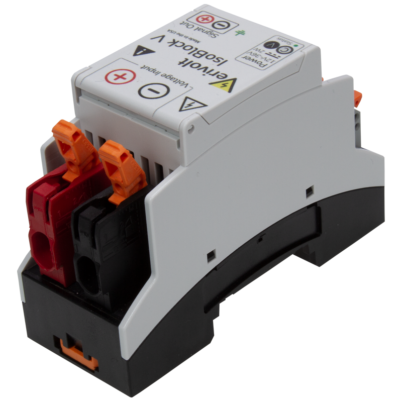
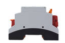
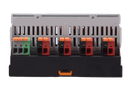
Compact Multi-Channel DIN Rail Integration
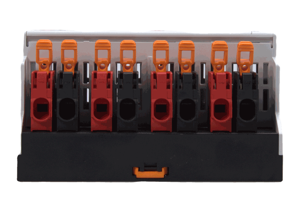
The IsoBlock V's 3.9" DIN rail footprint with four independent isolated channels reduces panel space and integration complexity compared to four single-channel modules. Spring cage connectors accept 20-6 AWG twisted pair cable from measurement sources to DAQ inputs. Low output impedance (20Ω per channel) supports cable runs to remote DAQ equipment.
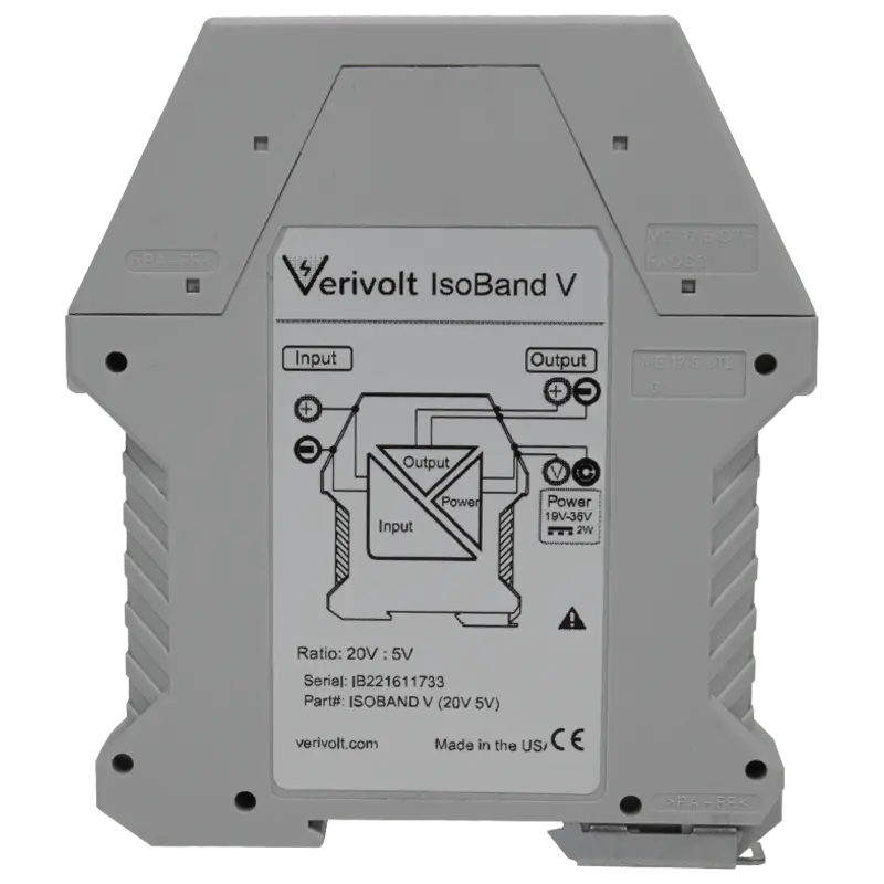
Future-Proof Analog Architecture
The IsoBlock V outputs differential ±10V (not current loops) maintaining resolution independence from the measurement instrument. A 16-bit DAQ system captures 16-bit resolution per channel; upgrading to 24-bit hardware in future projects automatically provides 24-bit resolution on all four channels with the same module.
Electrical Performance & Certification
Power consumption with excellent temperature stability (±50 ppm/°C gain drift, -25°C to +70°C operating range). Input-to-output linearity is <±0.04% per channel, enabling high-fidelity waveform capture across all amplitude levels. Common mode rejection reaches 112 dB @ 60Hz.
Frequently Asked Questions
We use “V” to denote peak voltage values, and “VAC” to denote RMS voltage values. The RMS-to-peak conversion factor is √2, approximately 1.42 (Vpeak = Vrms × √2 ≈ Vrms × 1.42)
For example, if a sensor specifies an input and output range of 100 VAC to 7 VAC, this means:
- It accepts an input of 100 Vrms, which equals approximately 142 Vpeak
- It outputs 7 Vrms, which equals approximately 10 Vpeak