


Product Details
Zero Flux Sensor
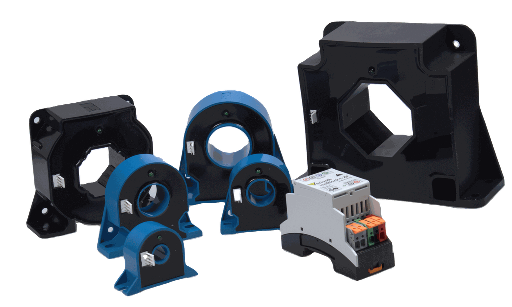
The IsoBlock I-ZF is a zero-flux closed-loop current sensor delivering <0.01% input-to-output non-linearity across 20A to 2000A DC measurement—or <0.005% in precision configuration. This zero-flux architecture eliminates the linearity drift and temperature compensation requirements of conventional open-loop Hall sensors, which typically exhibit 1-2% nonlinearity. The I-ZF also supports AC measurement from 100-2000AAC, making it suitable for three-phase systems, inverter output monitoring, and bidirectional current measurement where both positive and negative currents require equal accuracy.
Compact Form Factor
The compact form factor of the IsoBlock I-ZF module set allows users to setup high channel density monitoring systems, making it ideal for high performance compact systems.
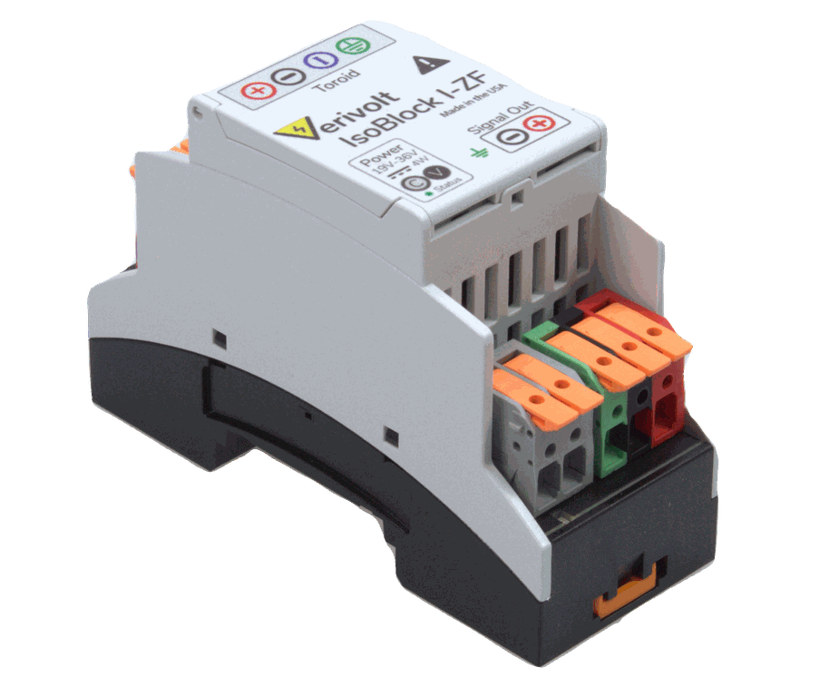
Three-Way Galvanic Isolation
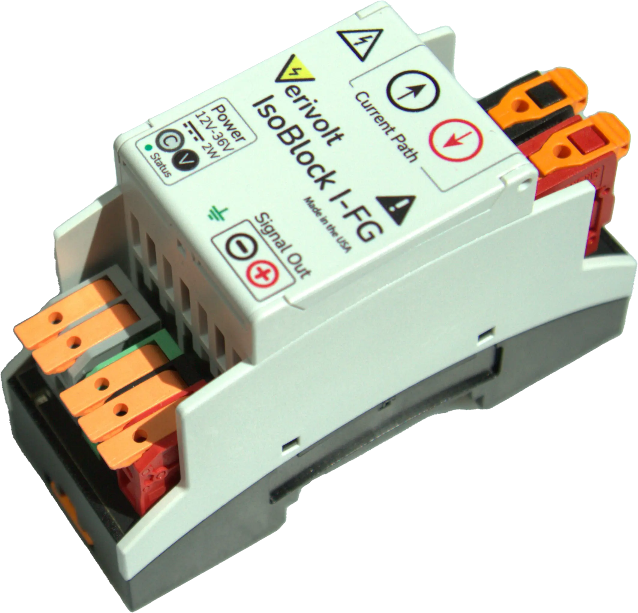
The I-ZF uses an aperture located at the center of the sensing unit where the conductor passes through to measure current flowing in the conductor. The sensor provides 5kV galvanic isolation (1 minute sustained) with 10kV transient withstand (50µs), protecting downstream electronics and enabling floating measurement in multi-voltage systems. Output is standard ±10V differential with 20Ω output impedance and <±500µV offset voltage, compatible with standard data acquisition systems and oscilloscopes.
Frequently Asked Questions
Yes, the IsoBlock I-ZF can measure both AC and DC currents, if they fall within the specified bandwidth in the attached datasheet.
The sensor’s accuracy is defined by one of the following formulas:
±(0.1% of reading + 0.005% of range) or ±(0.02% of reading + 0.005% of range), depending on the level of accuracy selected for the module.
For example, with an IsoBlock I-ZF (100A, 10V, 0.1%), a 50A current would result in an accuracy of: (0.1% × 50A) + (0.005% × 100A) = ±0.055 A.
RMS vs. Peak Notation (AAC vs. A): We use AAC to indicate RMS current and A for peak current. This helps users avoid manual conversions. For example, 100A corresponds to 100 A peak input, while 100AAC corresponds to100 A RMS input ≈ 142 A peak.
An IsoBlock I-ZF (100AAC, 7VAC) has a 142 A peak current range and a 9.94 V peak output.
The IsoBlock I-ZF (20A, 10V, 0.1%) can measure currents for ±20A and proportionally output a voltage of ±10V. The 0.1% accuracy of the sensor applies for the upper 10% of the range, which means that the sensor can accurately measure currents from ±2A up to ±20A. This result can be obtained when applying the following formula:
Accuracy = ± (0.1% reading + 0.005% range)
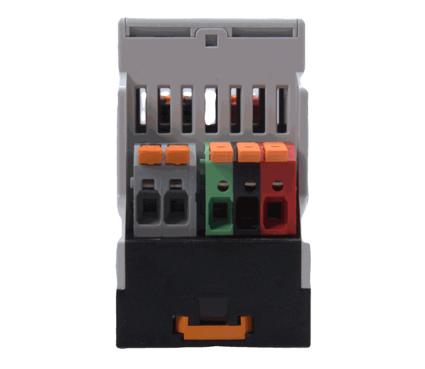
The IsoBlock I-ZF does not come with a prebuilt cable for the connection between the toroid and signal conditioning unit. However, it comes with the connector housing and crimping terminals to allow customers to build their own cable according to their requirements. The applicable cable area range is from AWG28-AWG22.
Additionally, we recommend that the cable between the two components has a length under 10 meters, in order to avoid any significant EMI or noise from affecting the measurements. For longer cables, it will depend on the environmental conditions in which the sensor is located in.